
Manufacturer and Exporter of : Compression Testing Machine, Electronic 4 Column Compression Testing, Electronic Compression Testing, CTE PRO, Analog Compression Tester
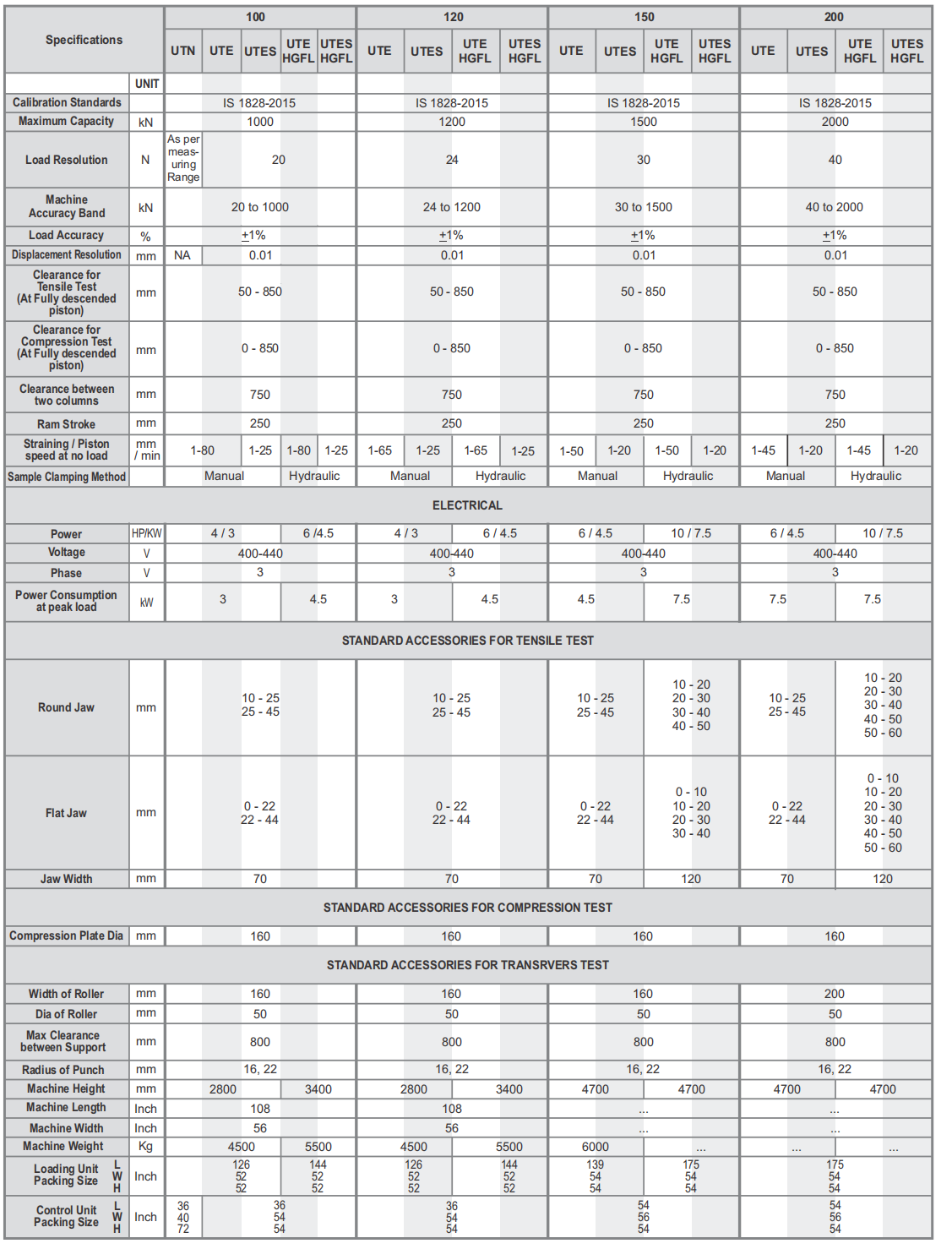
Universal Testing Machine - UTN


Features - Universal Testing Machine
- Loading accuracy as high as + 1%
- Suitable for variable speeds to suit a wide range of materials.
- Continuous roll autographic recorder supplied as standard to enable the study of the behaviour of materials.
- Motor driven threaded columns for quick effortless adjustment of lower cross-head-to facilitate rapid fixing of test specimen.
- High reading accuracy due to large size and design of dial.
- Wide range of standard and special accessories, including load stabilizer.
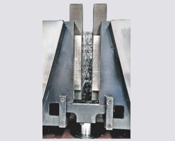
- Easy change from plain to threaded and screwed specimens.
- Large effective clearance between columns enables testing of standards specimens as well as structures.
- Simple controls for ease of operation.
- Robust straining frame of an extremely rigid construction.
- Safe operation ensured by means of safety devices.
- Fully enclosed and protected pendulum.
- Load Capacity : 100 kN, 200kN, 400kN, 600kN, 1000kN
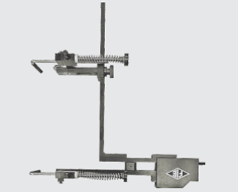
Pendulum Dynamometer
This unit permits selection of favorable hydraulic ratios producing relatively small frictional forces.
Pressurized oil in the loading cylinder pushes up the measuring piston proportionately and actuates the special dynamometer system.
The piston is constantly rotated to eliminate friction.
The dynamometer system is also provided with an integral damper and ensures high reliability of operation.
The load transmitted to the dynamometer is transferred through a pendulum to the load indicator.
Application
'FIE' Universal Testing Machines are designed for testing Ferrous & Non-Ferrous materials under tension, compression, bending, transverse, and shear loads. Hardness tests on metals can also be conducted.
Principle of Operation
- The operation of the machine is by hydraulic transmission of load from the test specimen to a separately housed load indicator device, which could be analogue, digital, or in the form of computer software
- The hydraulic system is ideal since it replaces transmission of load through levers and knife edges, which are prone to wear and damage due to shock on rupture of test pieces.
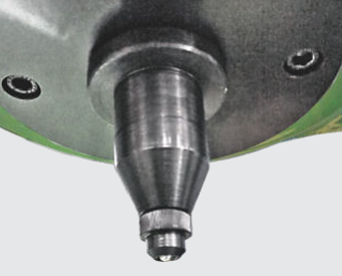
- The Load is applied by a hydraulically lubricated ram. Main cylinder pressure is transmitted to the cylinder of the load-sensing system housed in the control panel.
- In the case of analogue UTM, the load transmitted to the cylinder of the dynamometer is transferred through a lever system to a pendulum.
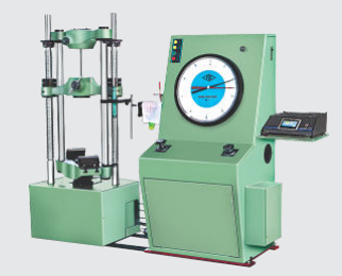
- Displacement of the pendulum actuates the rack and pinion mechanism, which operates the load indicator pointer and the autographic recorder. In the case of Digital UTM, the load is transmitted to the pressure cell and converted into load on the display unit.
Displacement
In the case of analogue UTM, an elongation scale, with a minimum graduation of 1mm, is provided to measure the deformation of the specimen.
in the case of Digital and computerized machines, an encoder is connected to electronic panel for displacement reading
Accuracy and Calibration
FIE Electronic Universal testing machine is closely controlled for sensitivity, accuracy and calibration during every stage of manu - facture.
Machine is calibrated over each of its measuring ranges In accordance with the procedure laid down in IS 1828: Part1.
FIE Electronic Universal Testing Machine complies with Grade “A” of class 1 of IS-1828-Part 1.
Windows based software feature
- Online graph on PC, Data analysis, Statistics, Point tracing, superimposing graphs to compare with standard, zooming graph etc.
- Report customization as per custom requirements.
- Video Extensometer compatible.
- R & N value extensometer compatible.
- Proof stress calculation from 0.1% to 1%.
- Integration of custom sample.
- Single point software calibration.
- Facility to export data to PDF, EXCEL & CSV formats.
- Unit selection for Real time Graph.
- Unlimited Test in single batch file.
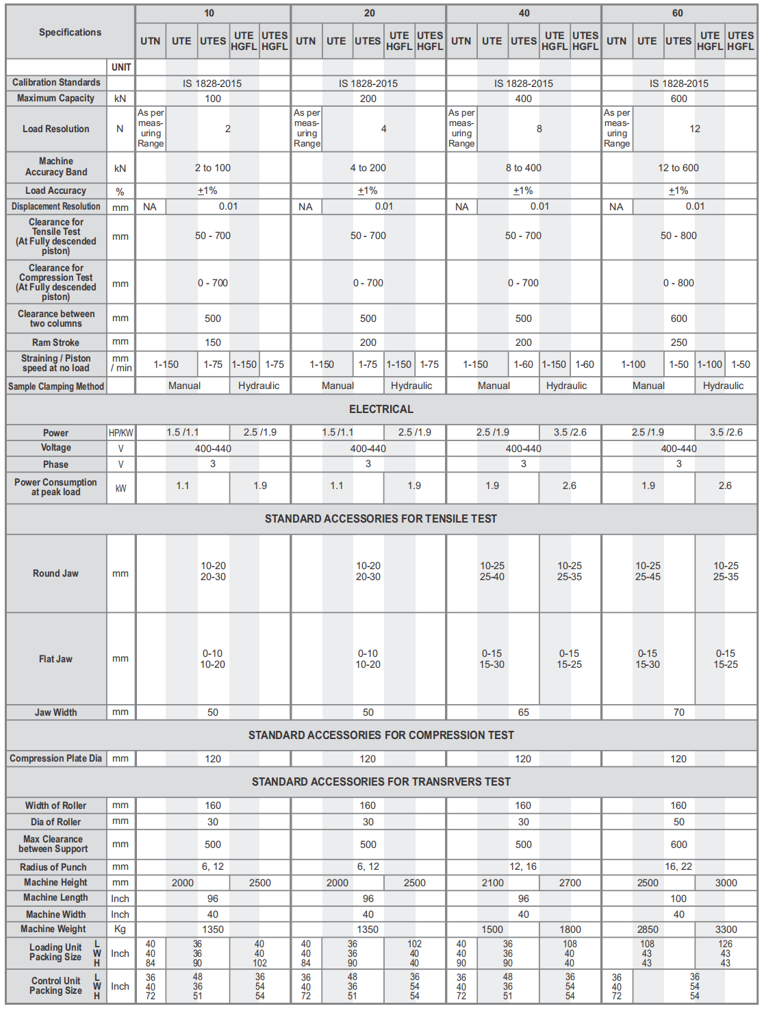
Technical Specifications - Universal Testing Machine
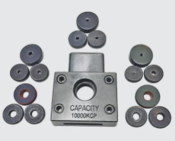
Accessories and Consumables - Universal Testing Machine
Analogue Cum Digital UTM machine Available for UTN series models
Panel with Touch screen Industrial PC Applicable for all models
Strand wire grips
Applicable for HGFL Models
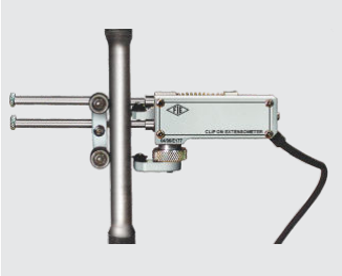
Electronic extensometer Applicable for all models
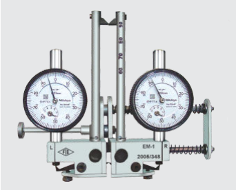
Mechanical Extensometer Applicable for all models
Attachment for Shouldered & Threaded Specimens M6 to M28 Applicable for all models
Brinell Hardness Test attachment Applicable for all models
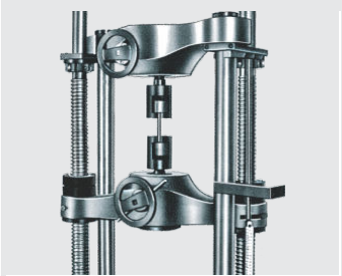
Adjustable Gauge length Electronic Extensometer
Video Extensometer Applicable for all models
Shear Test attachment Applicable for all models
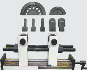
180° Bend Test attachment & mandrels Applicable for all models
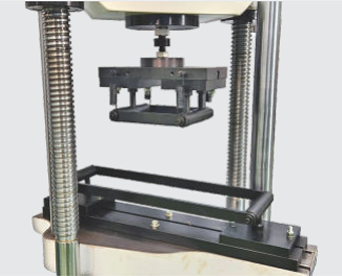
Flexural Test attachment Applicable for all models
Downloads - Universal Testing Machine